120 to 114 to 113 Twin Cam Engine Rebuild

Thanks for the tips. I'll take all the help I can get.

Do not trust that the rings have been pre-gapped, because mine weren't.
That's for sure.


Install one wrist pin clip into each piston before installing the pistons onto the rods, so that you will only have to fight with the last two clips.
Yup.


Double check the positions of the ring gaps one last time before you fit the jugs over the pistons.
Will do.


If you're using FM adjustable pushrods, put 4 full turns plus 5 flats on each one.
S&S recommends .125" preload for my premium lifters (4 turns at 32 threads/inch)


Disassemble lifters, drain oil.....
I'm doing the opposite here. I am filling them with oil using a vacuum bottle. I don't mind waiting for them to bleed down.

 
Pretty slick video of the Jim's Vacuum Pump method! I hadn't seen that before. Let us know how well it works. Here's another tip that I used to make pushrod adjustment much easier: I left the pushrod tubes off initially, installed the pushrods and rocker arm assembly, torqued them down to factory specs and then adjusted the pushrods. It was much easier to access the pushrod adjuster nuts this way. Once I had the pushrods adjusted per the manufacturer's instructions, I removed the rocker arm assembly and pushrods, installed the pushrod tubes and then reinstalled the pushrods from the top, followed by the rocker arm assembly and breather valves and then torqued to factory specs.
 
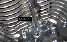
Your method sounds good to me. A few extra steps, but less chance for problems. Do you think this pushrod tube holding tool from Fuel Moto will work? It was included with the pushrods.

tool.JPG
 
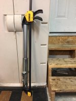
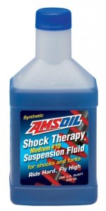
I changed fork oil and re-assembled the fork tubes. A bar clamp worked pretty good to get the caps back on without working up a sweat. Each fork takes about 24 ounces of oil. You just fill 'em to a specified height from the top with the tubes bottomed and the springs out.

IMG_1054.jpgSTM.jpg
 
Your method sounds good to me. A few extra steps, but less chance for problems. Do you think this pushrod tube holding tool from Fuel Moto will work? It was included with the pushrods.

View attachment 12254

I used the FM pushrod holder on my first build and it was a PITA, but but I got by with it (barely). The tension on the pushrod tube springs deformed the FM holder pretty easily. I had to reshape the holder several times. One day I stopped by my buddy's shop and saw him adjusting the pushrods on a motor without the pushrod tubes in place and it looked so much easier. I used his method on my second build and found It to be way easier.
 
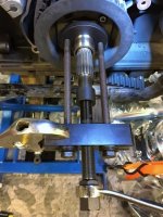
I pulled off the main shaft bearing race and pushed on a new one with a tool from George's Garage #620060. Worked as advertised. I had to apply some heat to the race with a torch to get it off. It was really on tight. I'm pretty sure I can continue with assembly now.

IMG_1055.jpg
 
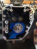
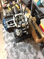
I checked the new Dark Horse crankshaft run-out in the engine cases today and found it to be .0006" which is excellent. I used the same measuring tool I posted earlier. Next I installed a new TC3 oil pump from S&S. The main benefit is two scavenge pump elements instead of the stock single element scavenge pump. This way, both the engine sump and cam chest are always properly scavenged of oil.

IMG_1056.jpg

 
Thank you for documenting and sharing your adventure. I've really enjoyed your pictures, links and write ups.
 
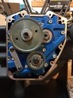
I installed the cams, cam plate, and gear drive today. It all went together OK and the gear drive backlash is perfect at .001". Gear drive should work great with the straight and true running crankshaft. Typical H-D tolerances require chain drive to tolerate more shaft runout.

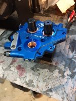
I used an S&S cam plate to go with the S&S oil pump and S&S cam gears. The S&S cam plate has bronze cam bearings. The sock cam plate runs the cam journals in the aluminum plate material.

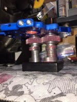
Here's the cams going into the cam plate using a holding fixture and tapered guides to make it easy:

IMG_1062.jpgIMG_1059.jpg

Next the cam plate goes into the cases with the cams and the outer gear set is installed. Be sure to rotate the flywheels while snugging up the oil pump screws to center the pump. I used a special spline wrench to hold the crankshaft while torquing the cam gear screws.

IMG_1064.jpgIMG_1065.jpg

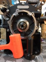
Then I went to the output side and installed the main bearing thrust washer, shaft seal, and the spacer the seal rides on. The seal is driven into place with a mallet and seal installation tool. I reversed the spacer when installing so the seal lips would not run on the tracks worn-in by the original seal.

IMG_1066.jpg

Next it's time to put the engine cases back in the bike!
 
Great report! Being meticulous like you always are will pay off Hulkss!! You and NGOT8R should open your own business!!!!!
 
I'm thinking I could drop my bike off next winter so you have a project to work on. It's really fun watching you build this motor and the steps your taking to share it with us.

Thanks
 
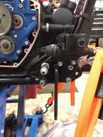
The engine case assembly is back in the bike! It went in easy. With a hex key wrench in the motor mount bolt you can flex the front lower mount to align the dowel pins with the engine. I discovered this when I was checking the mount bolt torques. Glad I did.

IMG_1070.jpg

Thanks to a tip from "NGOT8R" I had the proper wrench extension to torque the transmission to engine bolts. Keep it at 90 degrees to the torque wrench handle for correct torque readings.

IMG_1067.jpg

I put new grade 8 self locking flange nuts on the front mount bolts. The stock flat washers were all bent up and distorted.

IMG_1087.jpg

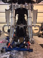
I also put the forks back on and a new chopped front engine guard from H-D.

IMG_1084.jpg

Thanks guys for the words of encouragement. I'll think I'll pass on becoming an independent bike repair shop.
 
man... this engine will be too good.. LOL!!!! 250K on the clock and will be running strong! I love all the details!!!!! Learning a thing or two as well... THANK YOU!
 
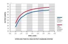
I put on a new voltage regulator from the H-D High Output Charging System kit p/n 29900028A. Might as well upgrade the charging system while it's all out on the floor. The big difference is about 50 percent more output at lower rpm's. This will help with the engine cooling fans I'm thinking about installing or my electric heated riding gear on cold days.

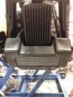
I bolted up the oil cooler and snapped on the cover with a piece of heavy duty stainless wire mesh (McMaster-Carr 85385T34) inserted to protect it from road debris that can bend the fins.

29900028HighOutputChargingSystem image.jpgIMG_1093.jpg
 
Hulkss- when do you anticipate completion?

As you guys probably noticed, I only work on this project a few evenings during each week. Combine that with my slow pace......maybe the middle of April. I want to be confident in the bike for a ride to Alaska leaving July 21st.
 
As you guys probably noticed, I only work on this project a few evenings during each week. Combine that with my slow pace......maybe the middle of April. My new wideband O2 engine control module is due from H-D about then. I want to be confident in the bike for a ride to Alaska leaving July 21st.

THAT will make for a good story!!!!
 
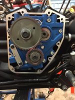
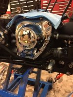
A little more done - emphasis on little. The cam chest is closed up. All I did was put assembly lube on the cam gears and install the cover. I've been taking the opportunity to clean & polish the bike piece by piece as I go. Normally, I hardly ever clean it properly.

IMG_1110.jpgIMG_1099.jpg

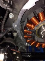
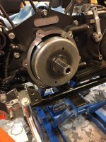
The alternator stator and rotor are installed. Getting that rubber seal through the case is a real test of finger strength. I used rubbing alcohol for lube as recommended. Careful putting on the rotor - the magnets pull hard until it is on all the way.

IMG_1096.jpgIMG_1098.jpg
 
Looks like you're getting close t being done with the bottom end. Did you get your jugs and pistons back after having received the special coating that you mentioned earlier? Things should begin to move along more quickly for you once you get the pistons, wrist pin clips and jugs installed. Trust me brother, I understand the desire to move slowly when lurking around in uncharted territory; it helps eliminate the possibility of mistakes. Once again, it looks to me like you're doing a fantastic job and you will also have plenty of time to test and evaluate before the Alaska trip.
 
I was reading the H-D manual and noticed something not in the the S&S instructions I was following. It says to install the front cam retaining ring (snap ring) with the sharp edge out. Man, I did not know they were that sensitive to "polarity". So, being paranoid, I opened up the cam chest to check it out. The snap ring on the front cam nose just about jumped out when I touched it with the snap ring pliers. :eek: You can see the ring in my previous post.

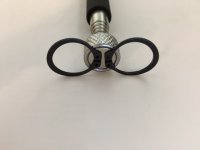
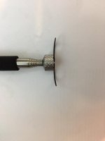
Looking at the ring it was bowed. Here's a couple pics with the one from the bike and another I had stuck to a magnet.

IMG_1109.jpgIMG_1106.jpg

I happened to have one more ring in my box of parts. This one was perfectly flat and installed nicely into the bottom of the groove (sharp edge out) and the cam end play checked perfectly at .010".

I did a quick search and some engines have failed from these rings coming off the front cam. I believe newer H-D cams have a wider snap ring groove and are made for the curved ring. My gear drive cam is made from an Andrews cam blank that has a narrower ring groove and the flat ring fits much better. Be careful with these in any case.

While I was in there I put in new H-D cam gear retaining bolts instead of the S&S ones (pic below updated).


Latest posts

Forum statistics

Threads
8,034
Messages
69,478
Members
15,208
Latest member
matta317